Technical Information
Installation
Model Ok702L
Step one:
Choosing a location for a Ok702L
There are two factors that must be kept in mind when considering a location
for the Ok702L: adequate sunlight and a suitable ambient temperature.
- Adequate sunlight
The Ok702L is solar-powered; to operate each night throughout the year it
requires an adequate amount of sunlight to recharge its batteries.
An introduction to the charging process
At dusk, the Ok702L will be "activated" and it will be discharging
its batteries while emitting light output. At dawn, it will turn off,
and its solar panels will begin to recharge its batteries. Sunny days
will result in the batteries recovering more energy than was expended
the night before. On days with little or no sun (due to cloud cover,
rain, or fog), the Ok702L may only recover a partial recharge, and thus
there will be a power deficit from the night before. THIS IS NOT A
CONCERN. All Carmanah Lights have excellent storage capacity and are
designed so they do not require sunlight every day.
With a fully charged battery, the Ok702L can operate for up to 600
hours without recharging, depending on the flash code and intensity
settings. For example, if we assume there is thirteen hours from dusk to
dawn, the unit is "on" and the battery discharging for ten hours out of
a 24-hour day. The unit will therefore last approximately 46 days (600
hours / 13 hours per day) without any sunlight for recharging. When
nights are longer (i.e.: 16 hours), the unit will last fewer days
without recharging (i.e.: approximately 38 days).
For the Ok702L to continue operating perfectly, it must recharge at
least partially before the 600-hour buffer is completely discharged.
However, this recharging can be spread over the 600-hour (46 day)
discharge time. Consequently, the unit can go several days without any
sunlight and then receive very little and still continue operating.
Despite the power storage capacity of the Ok702L, it is still important
to consider three factors when finding a location for the unit:
- Average daylight
Local weather conditions determine the amount of sunlight an area
receives each year. Areas with, on average, at least .75 hours of
sunlight per day or more (including the winter months) have adequate
sunlight for all Carmanah Lights. Most of the world receives this
minimum. The measurement to determine average daylight can be obtained
from your local weather office.
- Shade
Even the sunniest locations will not be adequate for proper installation
if the Ok702L will be in the shade for most the day. It is important to
ensure the unit will not be in the shade at least during midday.
- Winter
During the winter season, the sun is lower on the horizon. This has two
potential effects. First, obstructions such as trees, buildings, and
mountains that do not shade the Ok702L during the summer may come to
shade it during the winter. Second, for locations beyond 50° latitude
north or south, winter causes significantly shorter days and longer
nights. This may result in the unit not having sufficient recharging
time during the shorter days.
- Suitable ambient temperature
The temperature of the batteries in the Ok702L during recharging/discharging
affects the lifespan of its rechargeable battery power system, and
consequently the overall lifespan of the unit. Although the unit can operate
normally between the temperatures of -40° C (-40° F) and 80° C (176° F), its
expected lifespan may be reduced when the ambient temperatures are
consistently higher than 25° C (77° F) during recharging/discharging.
Although the Ok702L will operate most effectively in moderate areas, it
can certainly function in areas with ambient temperatures over 25° C (77°
F). A key factor will be that the unit is not usually charging/discharging
during the warmest part of the day. Unlike colder areas, hot areas generally
tend to have many hours of daylight, which allows the unit to fully recharge
every day. Since the unit does not need as much time to recharge, it will
fully charge and kick out of the recharging mode before the ambient
temperature is too high.
Step Two:
Activating the Ok702L
Simply remove the Ok702L from its shipping box and the unit is ready to go!
The light will automatically activate as soon as its photoelectric switch
recognizes it has been exposed to light.
Please note that the Ok702L also has built-in intelligence that automatically
deactivates it after 20 hours of complete darkness (i.e.: for seasonal storage
and/or transport). It is recommended you keep the unit's shipping box, in the
event you need to store or transport the unit at a future date.
ABC Technical Information on OkSolar Systems
Installations must me made by licensed technicians.
Technical Assistance or Advice
E-mail is the preferred method of communication and is
addressed within 24 hours, 7 days a week.
Please Allow 24-48 Hours for specific technical advise.
Any technical assistance or advice offered by Seller in regard to the use of any
Product or provided in connection with Buyer's purchases is given free of charge
and only as an accommodation to Buyer. Seller shall have no obligation to
provide any technical assistance or advice to Buyer and if any such assistance
or advice is provided, such fact will not obligate Seller to provide any further
or additional assistance or advice. Seller shall not be held liable for the
content or Buyer's use of such technical assistance or advice nor shall any
statement made by any of Seller's representatives in connection with the
Products or Services constitute a representation or warranty, express or
implied.
Installations must me made by licensed technicians.
OkSolar.com is not responsible for any typographical errors. Neither OkSolar.com
nor GeneralCommunications.com, corp. is not responsible or liable for errors in
installations. We offer industry-standard installations recommendations guide
lines; proper installation is the responsibility of the installers.
IMPORTANT NOTICE
The installer assumes full responsibility for the proper application and safe
installation of the units in accordance with these instructions, the National
Electric Code, and all other state and local codes and practices. OKSOLAR
accepts no responsibility for damages to property nor injury to personnel for
the improper use of this product nor its failure under any circumstances.
OKSOLAR warranty is limited to the replacement of the defective unit only if the
failure is the result of a manufacturing defect.
Limitation of Liability
UNDER NO CIRCUMSTANCES WILL OkSolar.com OR ITS AFFILIATES OR SUPPLIERS BE LIABLE
OR RESPONSIBLE FOR ANY LOSS OF USE, INTERRUPTION OF BUSINESS, LOST PROFITS, LOST
DATA, OR INDIRECT, SPECIAL, INCIDENTAL, OR CONSEQUENTIAL DAMAGES OF ANY KIND
REGARDLESS OF THE FORM OF ACTION, WHETHER IN CONTRACT, TORT (INCLUDING
NEGLIGENCE), STRICT LIABILITY OR OTHERWISE, EVEN IF OkSolar.com OR ITS AFFILIATE
OR SUPPLIER HAS BEEN ADVISED OF THE POSSIBILITY OF SUCH DAMAGE.
Some states do not allow the exclusion or limitation of incidental or
consequential damages, so these limitations may not apply to you. Neither
OkSolar.com nor its affiliates or suppliers will be held liable or responsible
for any damage or loss to any items or products connected to, powered by or
otherwise attached to the Product. The total cumulative liability to Customer,
from all causes of action and all theories of liability, will be limited to and
will not exceed the purchase price of the Product paid by Customer. This
warranty gives the Customer specific legal rights and the Customer may also have
other legal rights that vary from state to state.
Communications products: Please be aware that the wireless portion of the system
must be handled with care and must be installed by an installer with some notion
of radio devices. We attach the radio specifications so that the installer will
be able to make any necessary modification to the radios.
Technical Support will be addressed only by email check our contact information
We offer design assistance on hourly basis minimum 3 hours Contact Us for
Pricing
Determining the Correct System:
To determine if IQUPS Power system will meet your solar
power requirements, first choose what DC voltage your system will operate on,
then calculate the Total Equipment Load in Amp-hours per Day. Next, looking at
the map of the U.S., determine your Solar Resource. Then, using the selection
matrix on the page, choose the appropriate system.
We offer design assistance on hourly basis minimum 3
hours contact you sales rep.
This information applies to all systems :
Allow the system to charge its batteries four to seven days of full
sunlight before switching on the Inverter for first time or after a long period
of storage. Very Important!
Graphic Installations Catalog Click on Pictures for
technical information

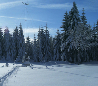
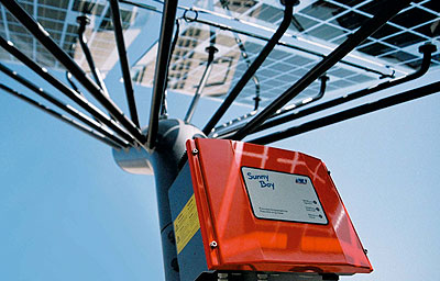
Solar Trees AC, Daily out Put. Pure Sine wave
utility grade electricity
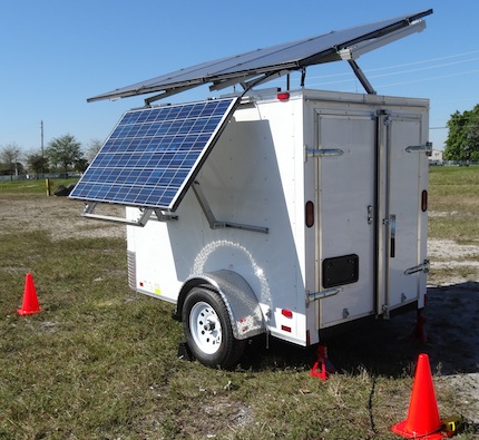
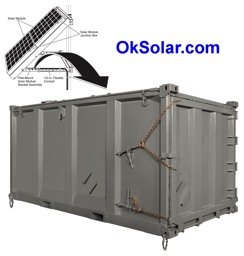
TSPDC Transportable (Trailer-Modular Power Storage)
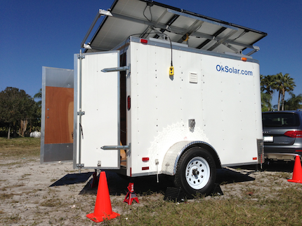
Modular Energy Storage 16KWh Battery Storage, Large Scale Battery Storage new
modular design Plug and Play IQUPS Technology that lets Clients like Hospitals,
Airport, Industries, and Utilities scale up as is needed.
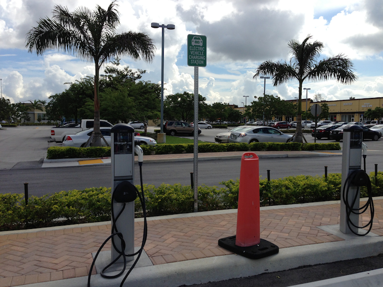
Electric Vehicle Charging Station Solar Powered
OkSolar.com High Reliable Systems
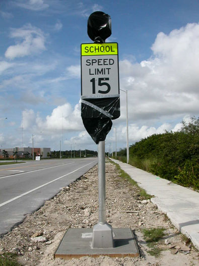
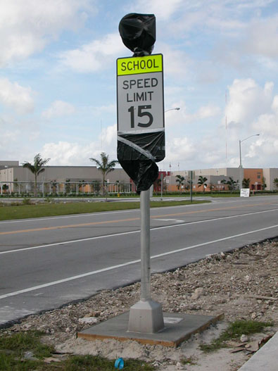
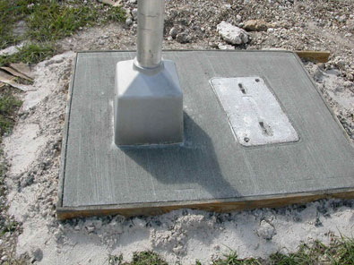
Traffic Concrete Pedestal Installation
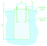
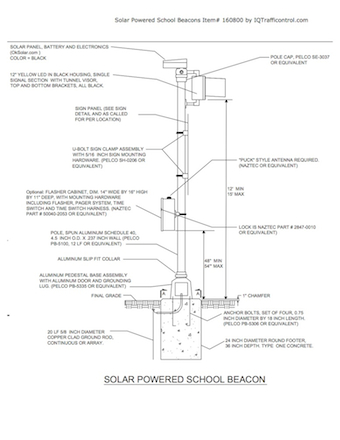
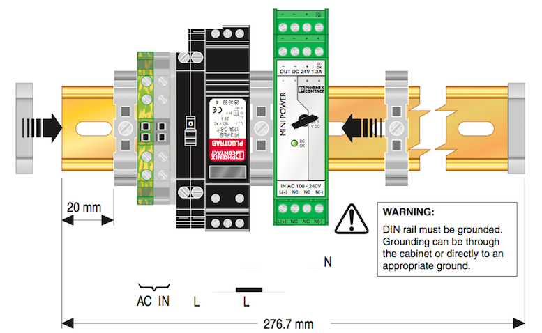
Phoenix Contact Installations
OkSolar High IQ Simple Connections line of
Charge Controllers
Microproccessor
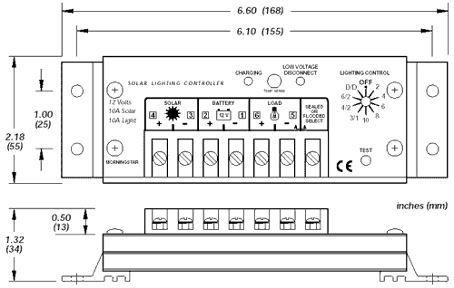
Connections are simple follow the pictures
Connect slots 4 and 3 (SOLAR) to solar panels.
Connect slots 1 and 2 (BATTERY) to the battery.
Connect slots 5 and 6 (LOAD) to the lamp.
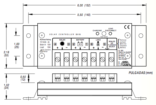
Batteries Technical information:
-Batteries
and Solar Modules Diagram of Connections
-Batteries Instructions
-Buried Batteries Systems
-Video of
Battery Connections
-Video Battery Serial Connections
-Video Battery Parallel
(Serial + Parallel)

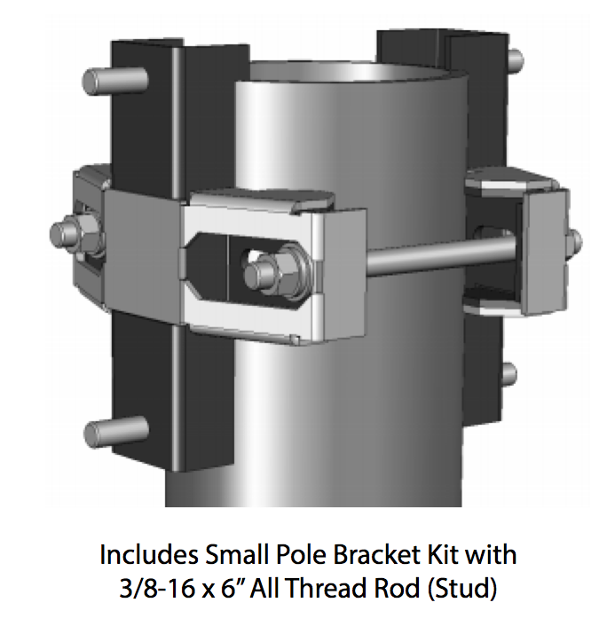
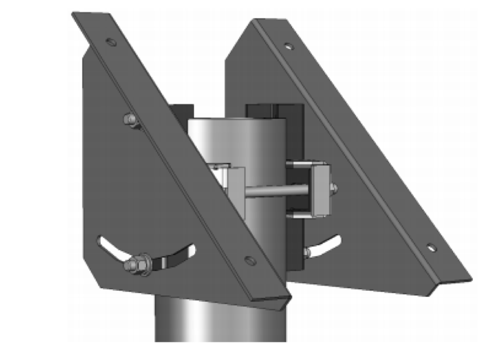
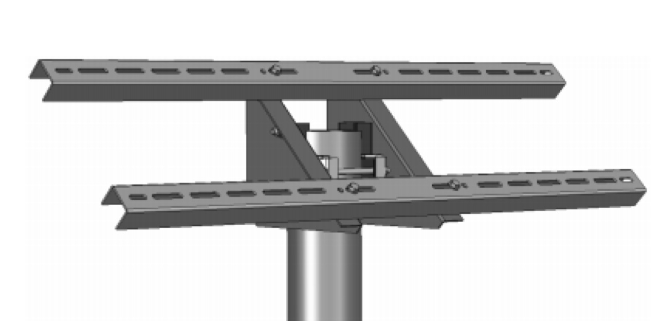
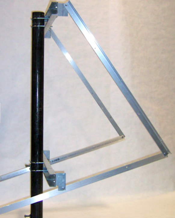
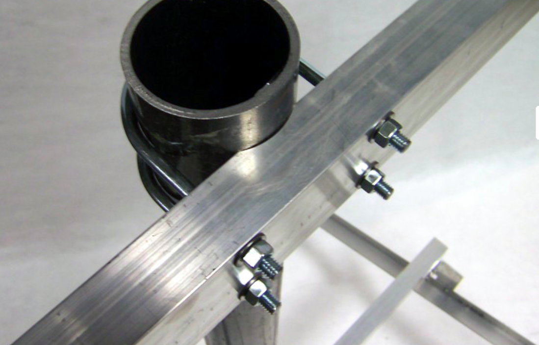
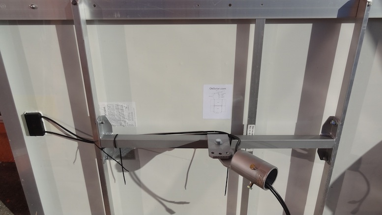
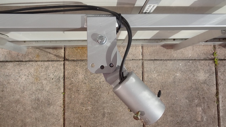
Solar Side Pole Mounts -
STANDARD-IN-PV-MOUNTING-STRUCTURES.pdf - How
to setup Structure for a Solar Module

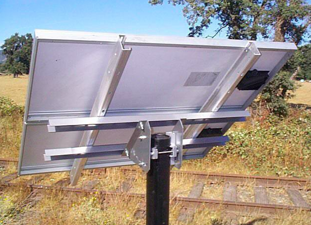
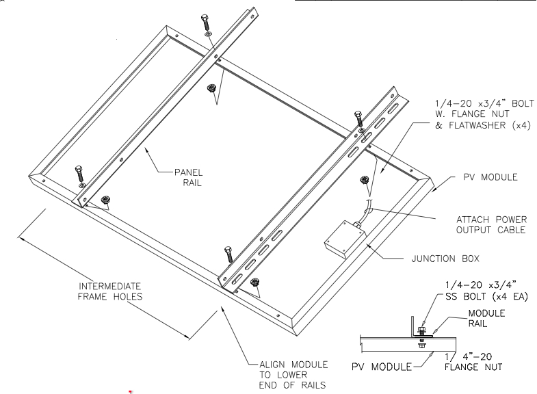
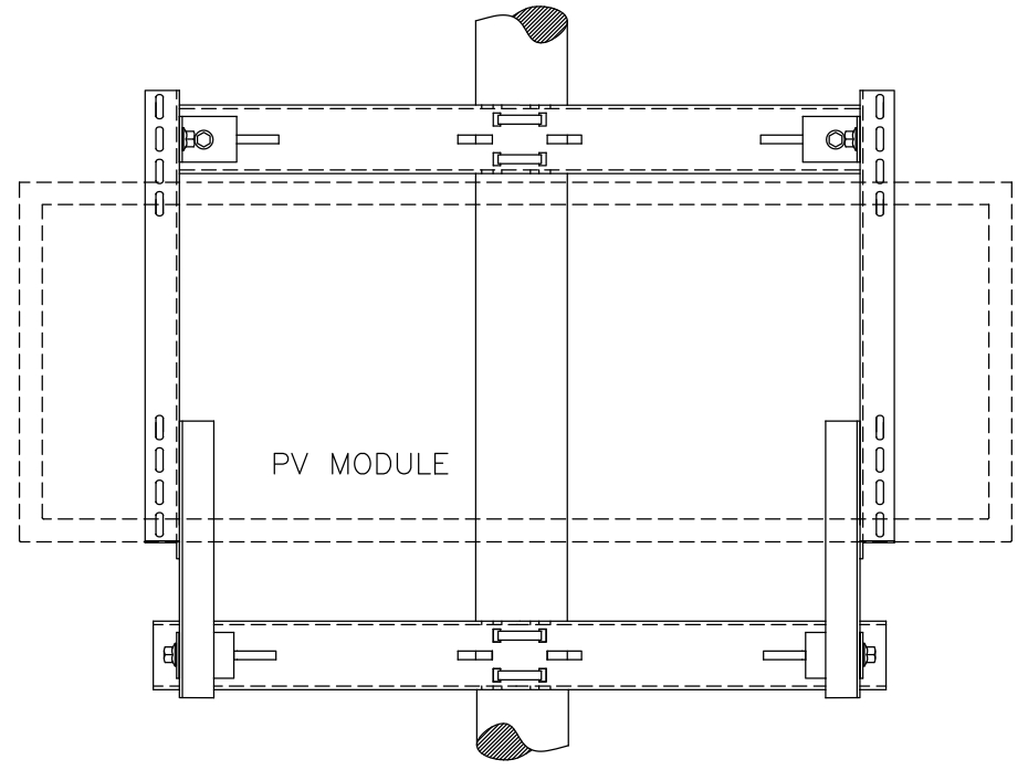
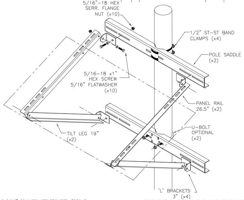
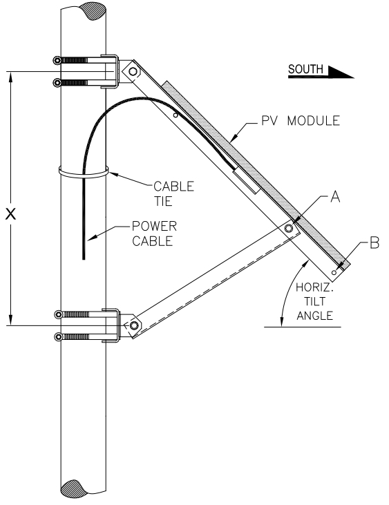
Solar Side Pole Mounts

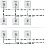
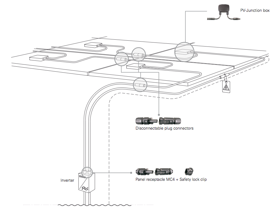
Solar Module Wiring
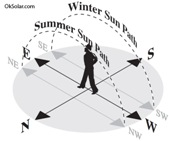
-Angles of Orientation
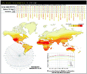
-World Daily Solar Insolation Map.
-Solar Modules Technical Information
-How to install a solar panels
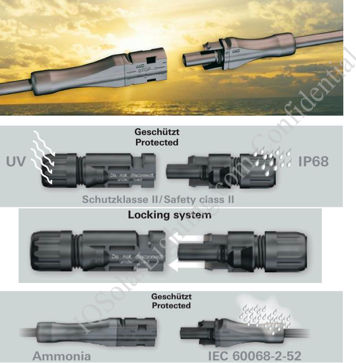
-Solar Modules Wire Connectors
-Daily Solar
Radiation
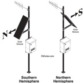
Solar Module Orientation If your site is located in the
northern hemisphere, face the solar module true south. Similarly, if your site
is located in the southern hemisphere, face the solar module true north.

Solar Modules interconnects


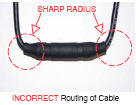
Solar LED Combiner box

Solar LED Street Lighting installation Manual
Enclosures: Installations
Pole Mounting
Enclosures Mounting Instructions
Enclosures Buried Batteries for LED Solar Systems (7 Inches Minimum Gravel
Base.)
Customers have poured concrete boxes into the ground and then placed a OkSolar
Box inside the concrete box. Air ventilation provisions and drain system on the
bottom (to be addressed by the installer according to the particular
application) are recommended for these types of installations.
Foundation in Figure is given as only a general guide. The contractor has the
responsibility to determine the dimensions and type of foundation demanded by
the soil conditions at the installation site.
If you are burying them to keep the batteries cool then you won't need the
insulation. However, if they are burying them to keep them from view then I
would suggest using the insulation.
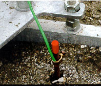
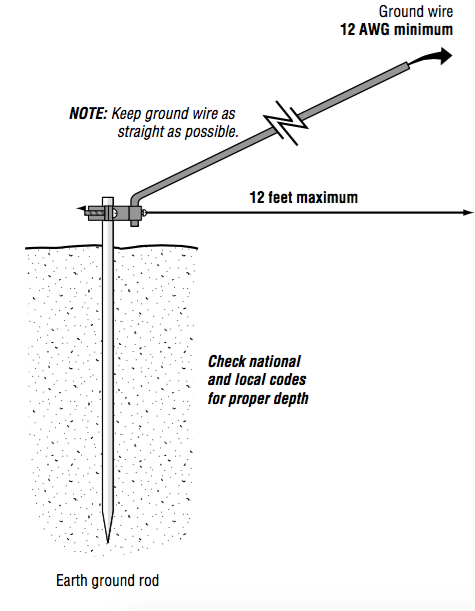
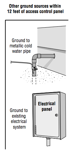
Nuts and Bolts of Grounding
Traffic systems

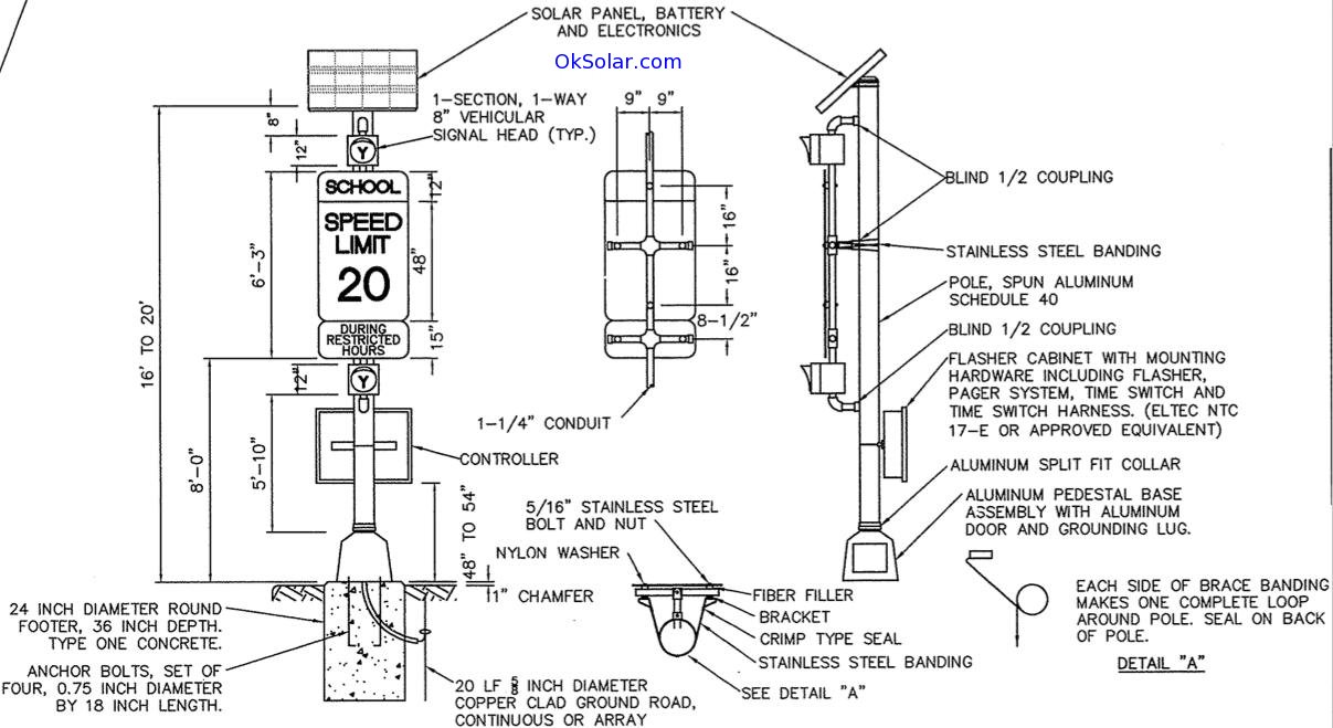
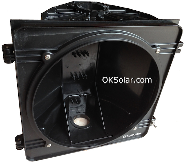
Traffic Flashers:
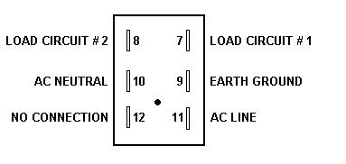
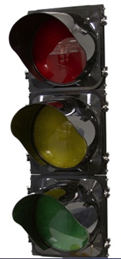
Polycarbonate Signals Specs Click on picture
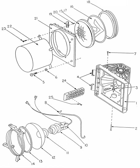

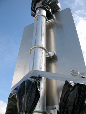
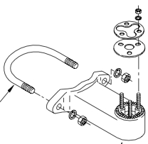
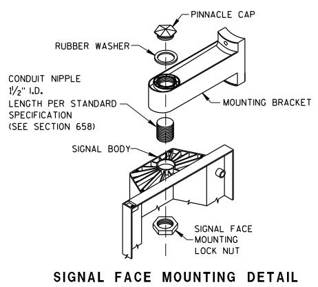
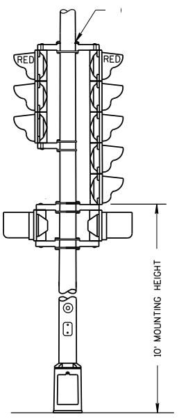
-Traffic
Aluminum Pole installation
-Traffic
Concrete pedestal installation
-Traffic Installations Parts

TSPDC Transportable (Trailer-Modular Power Storage)
1.
After Towing, Secure TSPDC3.5 Trailer by:
a.
Install Trailer Double Locking Jack Stands.
b.
Position the 2 Tires Stoppers.
c.
Position the 2 cones.
2.
Switch ON the Solar Array.
a.
Switch ON PV DC Breakers.
b.
Switch ON Battery Bank.
c.
Unit will start charging independently of the
solar array’s position.
d.
Allow the system to charge its batteries four to seven days of full
sunlight before switching on the Inverter for first time or after a long period
of storage. Very Important!
3.
To maximize the Solar Array output by position the solar array in an
angle.
a.
Unlock the solar array by removing the leg pins on
the top and side facets (four pins total).
b.
Switch ON the Actuator.
c.
Use Pendant Up-Down to adjust inclination of the
solar array. Warning: never raise the actuator when the pins are in place on the
top facet of the array. Doing so will result in damaging the panels and
actuator.
d.
For long stationary periods or in windy
conditions, use the locking pins to secure the solar array on the top facet. Use
the actuator to lift the panels to position and insert the pins in each leg,
then lower the actuator so that the weight is supported by the locking pins.
4.
Switch on Inverter AC
a.
ON AC Breakers internals and externals.
b.
Connect AC Loads.
Important Safety Instructions READ AND SAVE THESE
INSTRUCTIONS!
This manual contains important safety instructions for the TSPDC Transportable.
Read all instructions and cautionary markings on the TSPDC Transportable and on
any accessories or additional equipment included in the installation. Failure to
adhere to these instructions could result in severe shock or possible
electrocution. Exercise extreme caution at all times to prevent accidents.
Solar Array: we recommend fold solar array down in winds over 75mph.
Batteries initial: Allow the
system to charge batteries 4-7 days of full sun before Staring the Inverter.
Grounding: System grounding is the responsibility of the operator or installer.
Grounding requirements may vary by location and or Country depending on the
local electric code.
Note: OkSolar.com/GeneralCommunications.com Corp. cannot be responsible for
system failure, damages, or injury resulting from improper installation or
operation of their products.
TMSPDC Transportable
Modular Trailer Customer Operation PDF file
TMSPDC Transportable
Modular Trailer Customer Inverter Operation PDF file


Area Lighting Poles
All OkSolar poles are designed for ground mounting. Local soil conditions
determine the type of foundation required for each pole.
To select a pole, first add the weights and EPA's of the
mounting brackets and luminaires to get the combined load per pole. The wind
speed is determined by local conditions. The mounting height can be determined
by the luminarie manufacturer's specifications. Choose the wind speed category,
then the column that exceeds the combined load in weight. Move down the column
to the desired weight, then to the first pole that exceeds the combined load
EPA. This should be your best value. Remember the pole capacity must exceed the
combined load in both weight and EPA.
The pole capacity chart has been calculated with mounting
at ground level and 1.3 gust factor included. No provisions have been made for
banners, pendants, signs, flags, overhead wiring or other items that might be
fastened to the pole.
Local soil conditions determine the type of foundation
required for each pole. foundation in Figure is given as only a general guide.
The contractor has the responsibility to determine the dimensions and type of
foundation demanded by the soil conditions at the installation site.
The capacities shown are based on a 24" off center load. This is usually the
most conservative configuration. We have extensive charts for other wind, weight
and luminaire mountings. If we know your application, we can provide you with
the most economical pole.
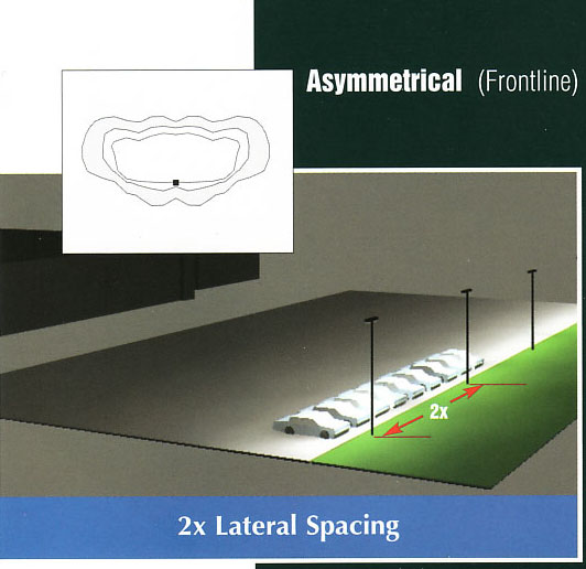
Poles Spaicing
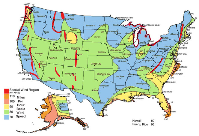
Poles wind Load
Poles Wind Load ISOTACH WIND MAP 50 YEAR MEAN RECURRENCE
ISOTACH WIND MAP
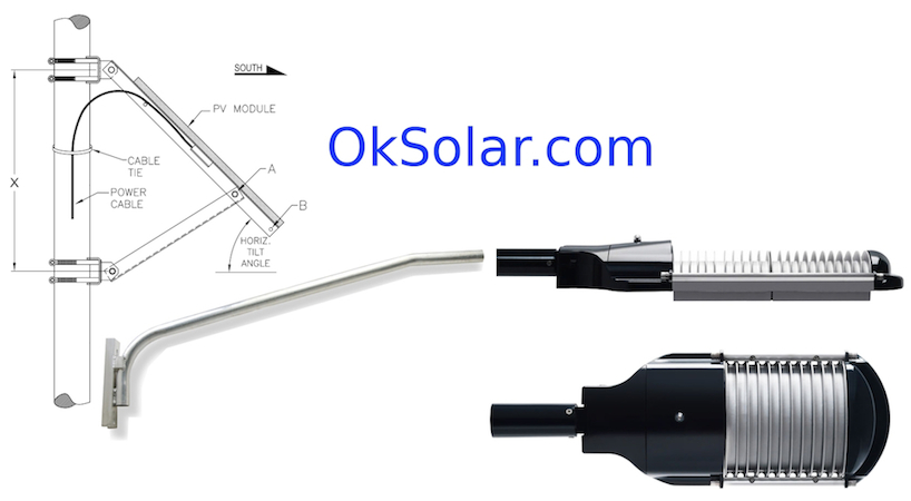
Bullet Proof Lighting


How to install a Bullet Proof LED Lighting Protection
Applications of bullet-Proof Installations lighting, vandalism,
shields, shield, vandal, bullet-proof, bulletproof, protection,
protect, resistant, safety, polycarbonate, Torsion Flex, Aero
Thermic, thermo, pistol, guard, proof, shoot, shot out, lights,
light, street, roadway, area, shoebox, flood, wallpack,
wallmount, post-top
Lighting information:
A lumen (lm) is the unit of measurement for the amount of light
emitted by a light source. A 60-watt light bulb emits 730 lm,
while a 50-watt halogen lamp has an output of approximately 900
lm.
What does "Candela", "Lumen", etc. mean?
Lighting Principles and Terms.
Solar LED Color Chart
What is Color Temperature?
Communications Radio Installations
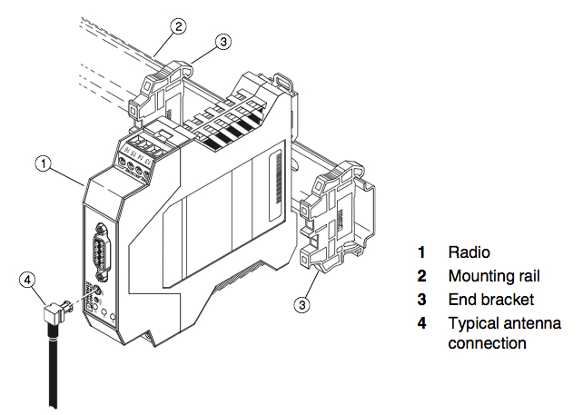
 How to install a Security PTZ Cameras.

Electronics LOW Pressure Ballast
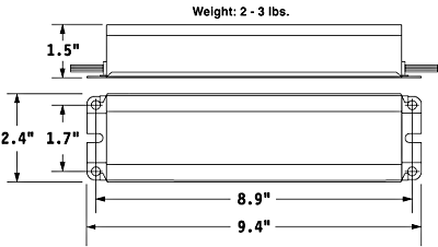
For the Ballast to Correctly Start the Lamp, the Lamp must be positioned within
one inch of a grounded metal Surface. Lamp Requeire about 10-16 minutes to reach
maximun output
Ballast
Testing Low Pressure Ballast: here are a couple things to consider when testing
the ballast without the lamp.
-The ballast should still draw a little current from the input voltage source
even without the lamp. The 12 VDC model will draw about 0.35 A and the 24 VDC
model about 0.20 A.
-The output voltage can also be checked but you must have a high voltage and
high frequency meter. If not, your meter could be damaged. The output voltage of
the 12 V model is about 360 Vrms @ 45 kHz. The 24 V ballast will be about 500
Vrms @ 35 kHz.
-If the ballast fails, it generally should not cause damage to the lamp.Wiring
connections the LPS40B
-Ballast Installation
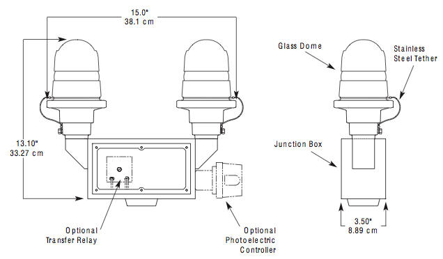
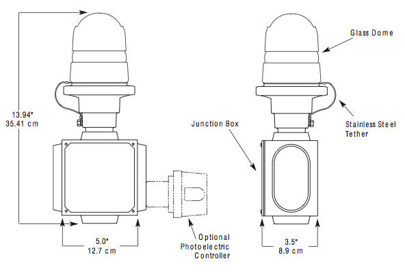
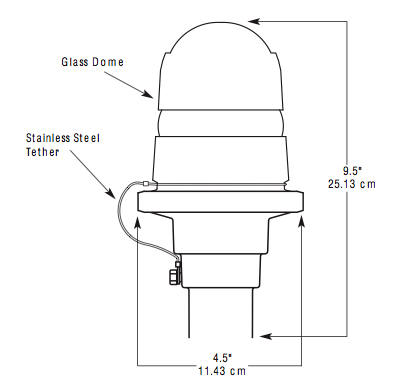
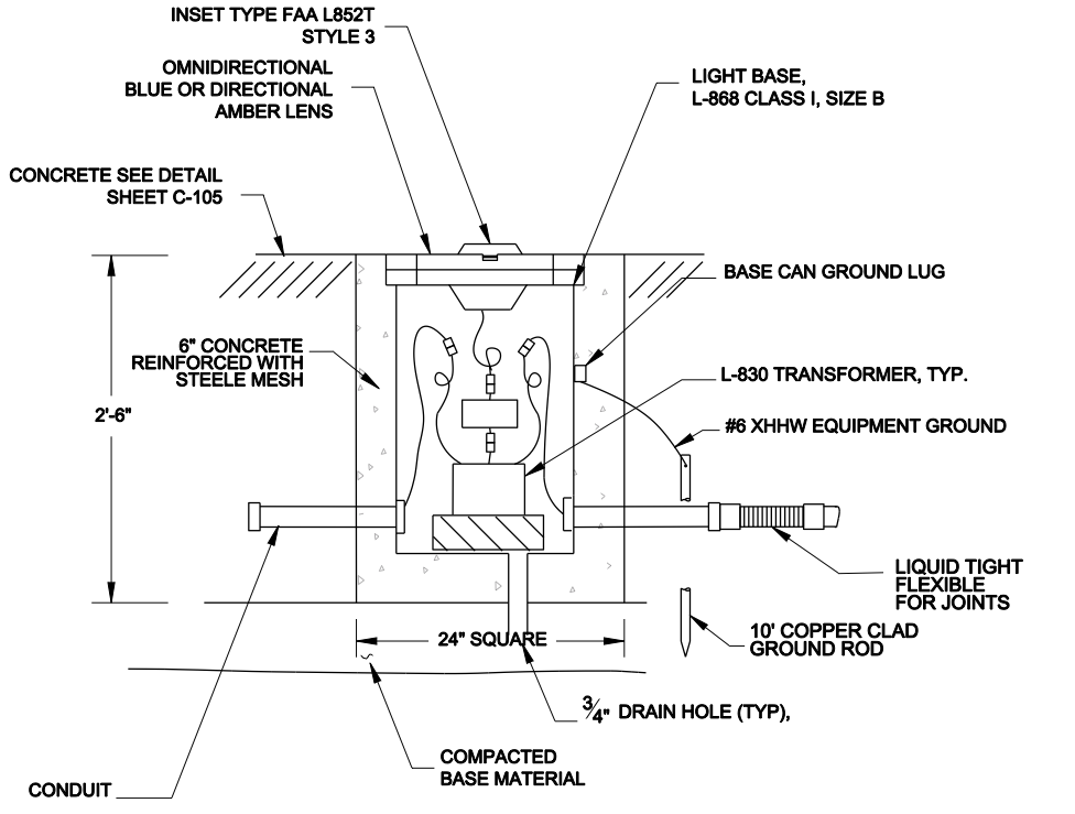
Solar Powered Beacons
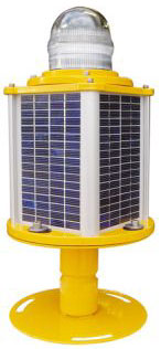

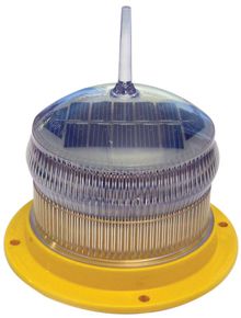
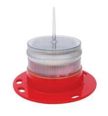
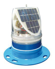
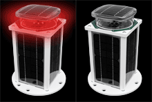
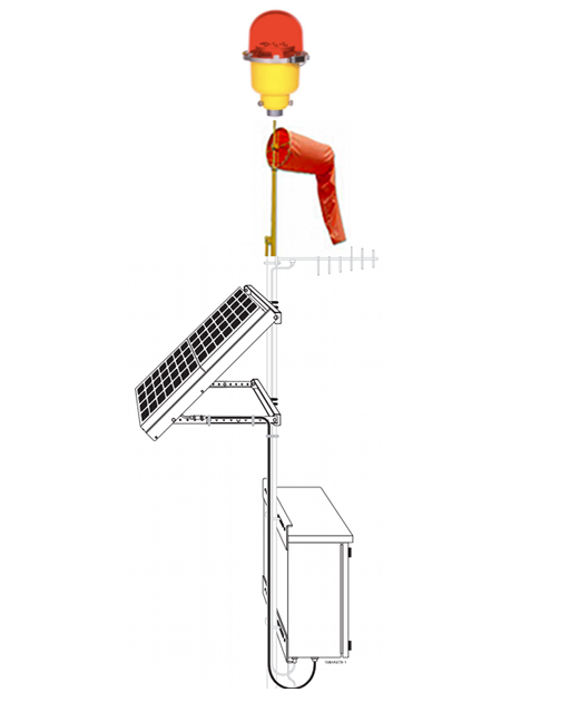
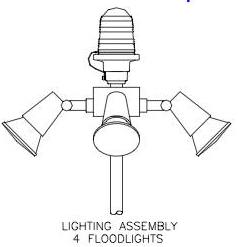
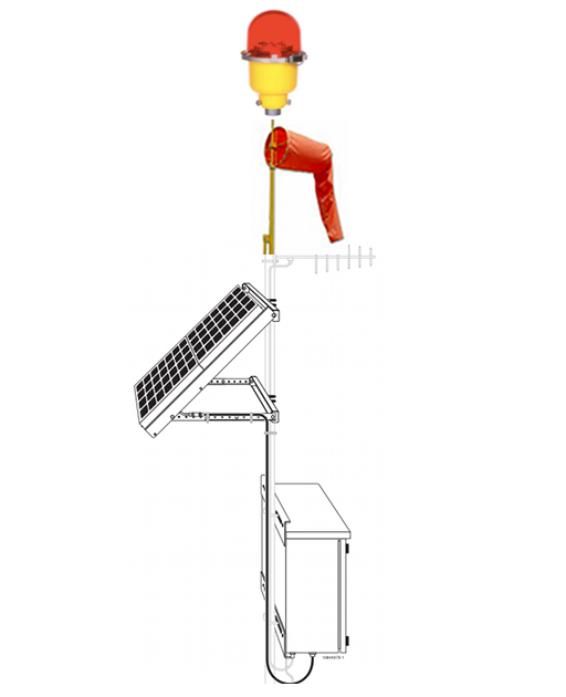
Solar Powered Obstruction Lighting US Department of
Transportation
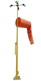
Wind Cones, FAA Wind Cone Solar Powered

Timers
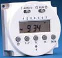

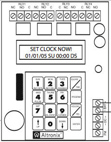
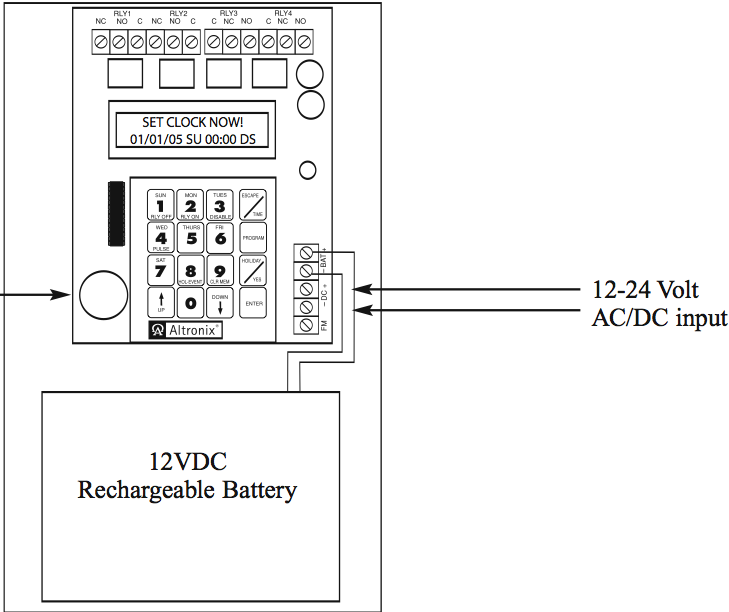
Programing instructions in PDF
365 Day 24 Hr 4
Channel Annual Event Timer
Additional instructions on keypad installation
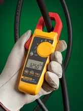
Calculations
-Voltage Drop Calculation
-Metric Voltage Drop Calculation
-Power Calculation
-Battery Power Calculation
Energy Management
At 1kVA output 3.4kVA runtime for each battery configuration is
as follows:
• 12KWh – 12hours
At 2kVA output 3.4kVA runtime for each battery configuration is
as follows:
• 12KWh – 5 hours
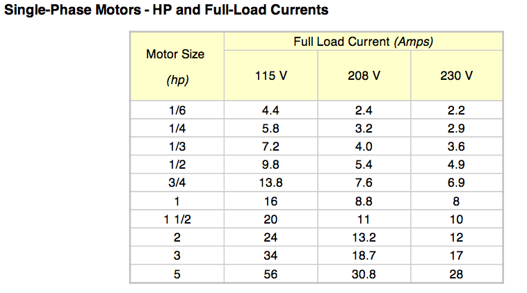
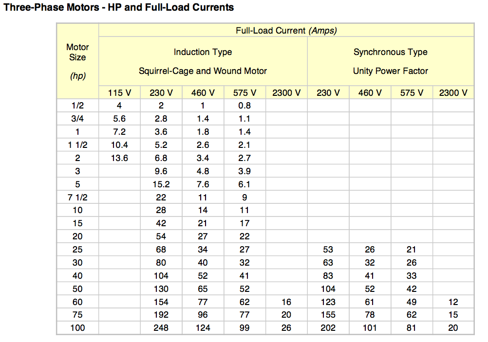
As a "rules of thumb" amps horsepower rating estimated
115 Volts motor - single-phase : 14 amps/hp
230 Volts motor - single-phase : 7 amps/hp
230 Volts motor - 3-phase : 2.5 amps/hp
460 Volts motor - 3-phase : 1.25 amps/hp
Single-Phase Motors - HP and Full-Load Currents
Three-Phase Motors - HP and Full-Load Currents

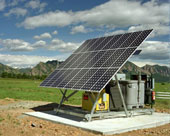
Solar Powered DC and AC units diagram


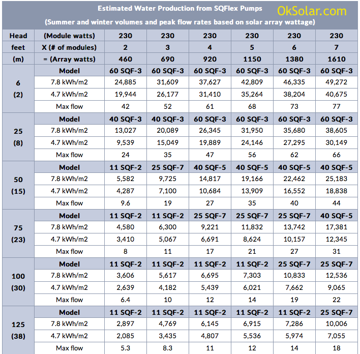
Solar water pumps
Estimated Water Production from SQFlex Pump


** 6kWh/day of power generation
Four 300-Watt Solar Panel
300 watts x 4 = 1200 Watts/hour X 5 Hours = 6,000 Watts Daily
*16 (6 V) 400 amp-hour sealed AGM batteries
=24 Volts x 4 Banks x 400 Amps = 38.400 Watts
38.4 kWh battery storage capacity at 24 Volts

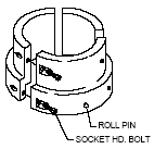

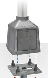


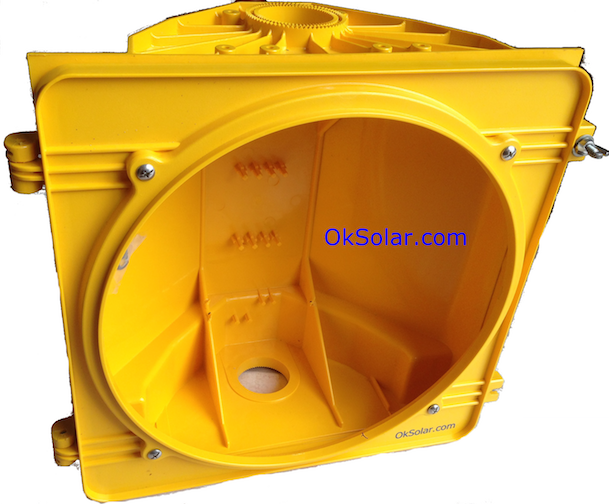


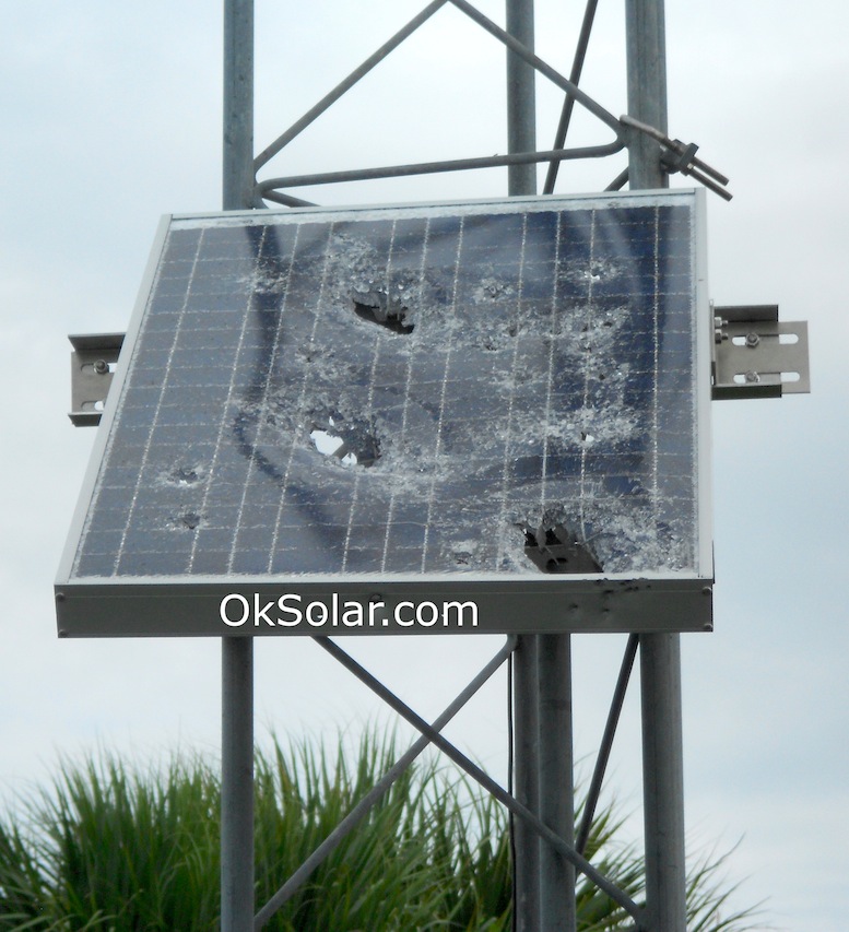
Ballistic Protection: Stop this from
happening at once! Item#54780
-
Ballistic Protection - Bullet Proof Shields
-
This patented* shield incorporates leading edge
technology to provide maximum ballistics resistance.
-
The shield is primarily constructed of dual layer
polycarbonate sheets which are UV stabilized.
-
Designed to stop small arms fire .22 to .44 caliber





OkSolar.com Serving The Industry Since 1988.
All rights reserved. All trademarks or product names mentioned herein are the
property and responsibility of their respective owners.
Credit Pictures provided by PIX along with DOE/NREL
V7.17

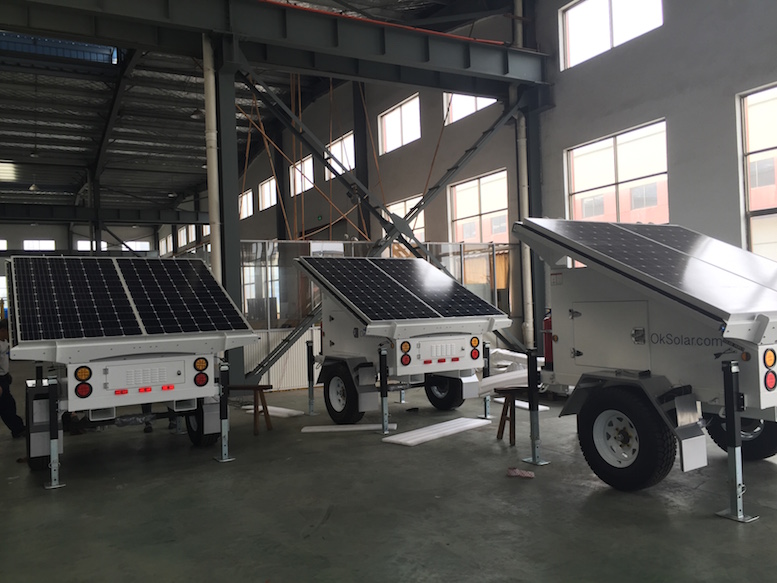
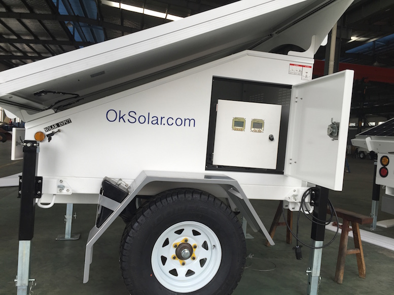
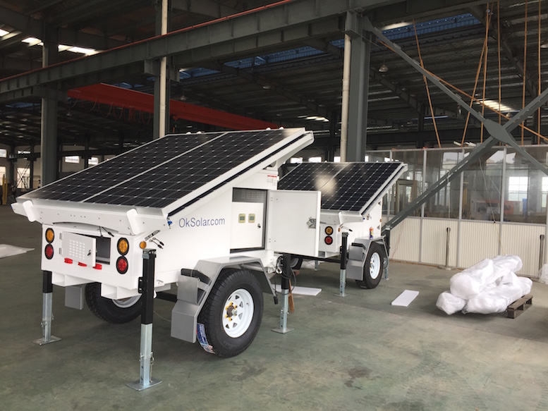
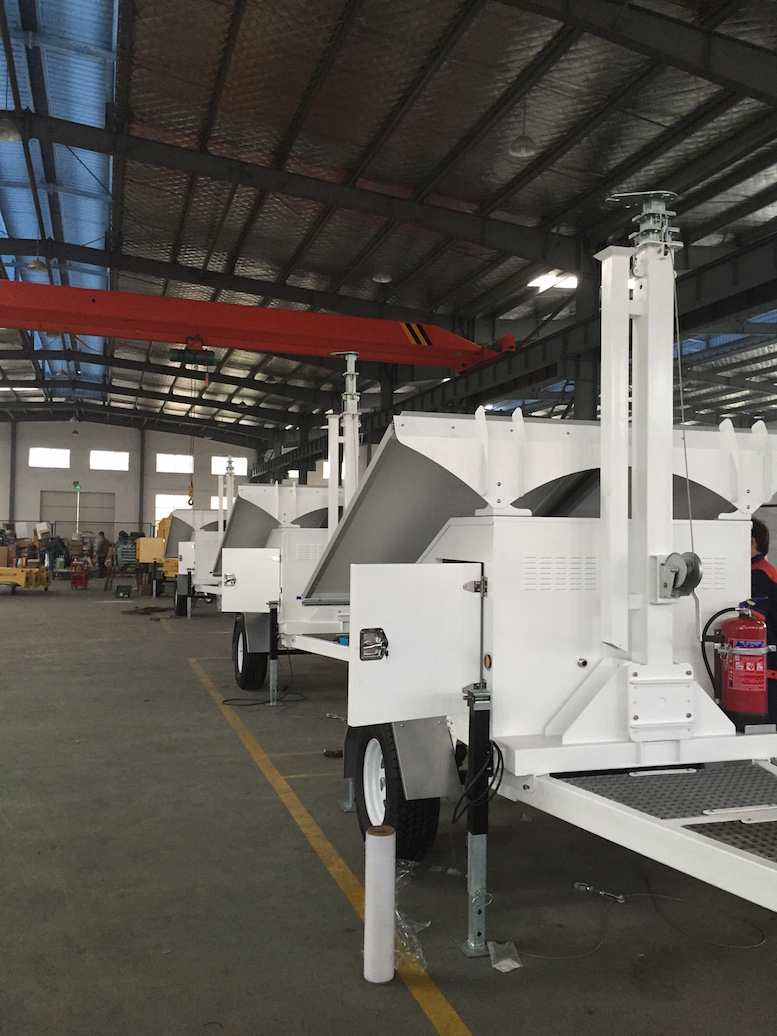
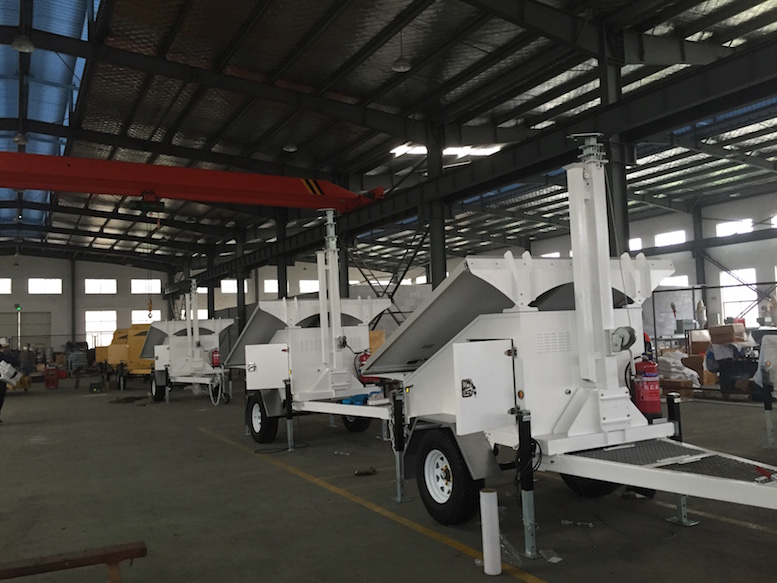
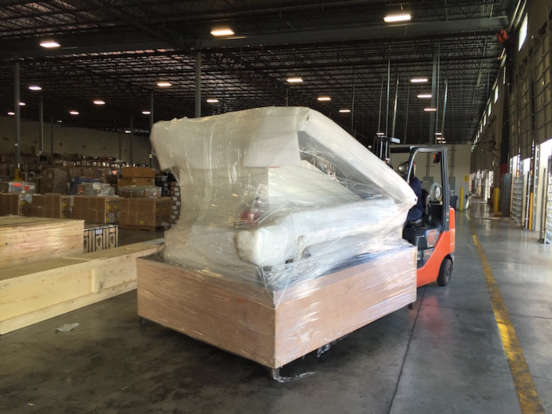
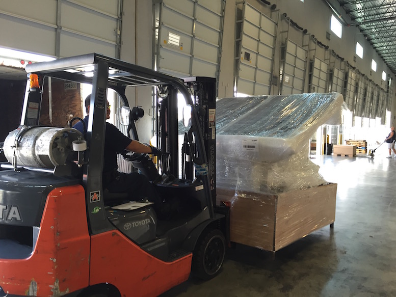
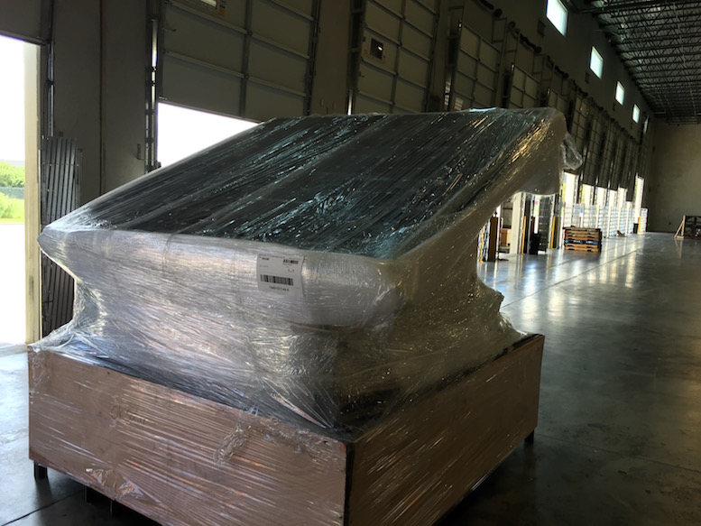
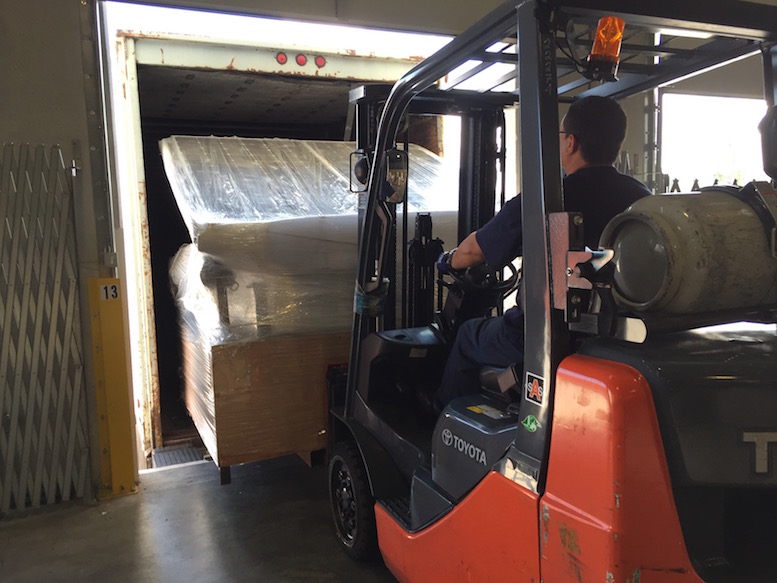
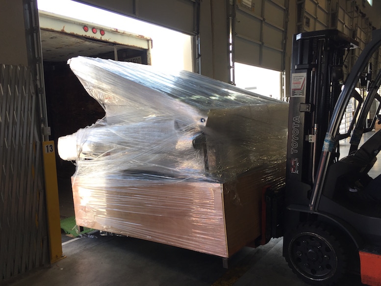
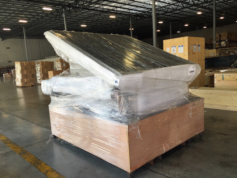
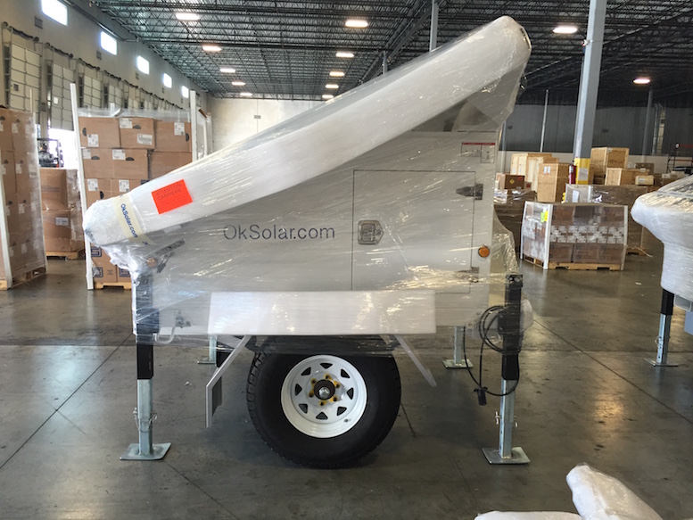
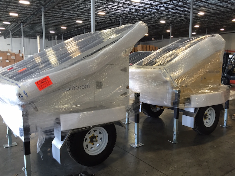
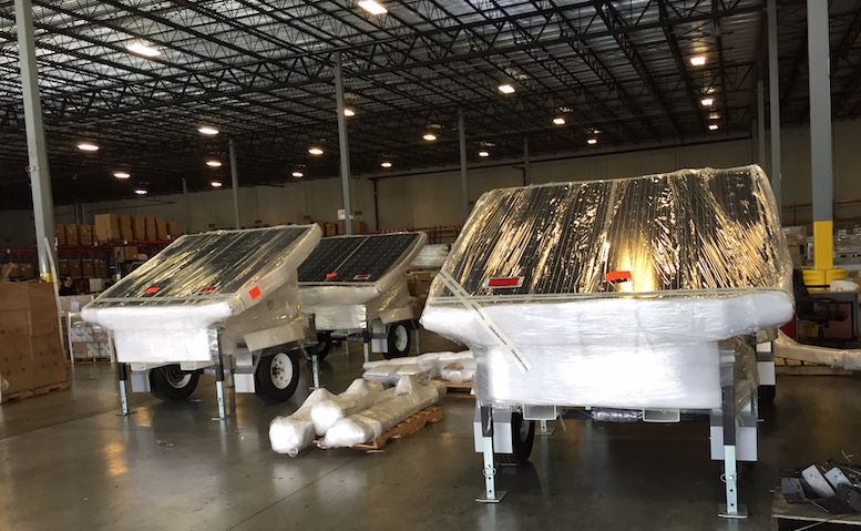
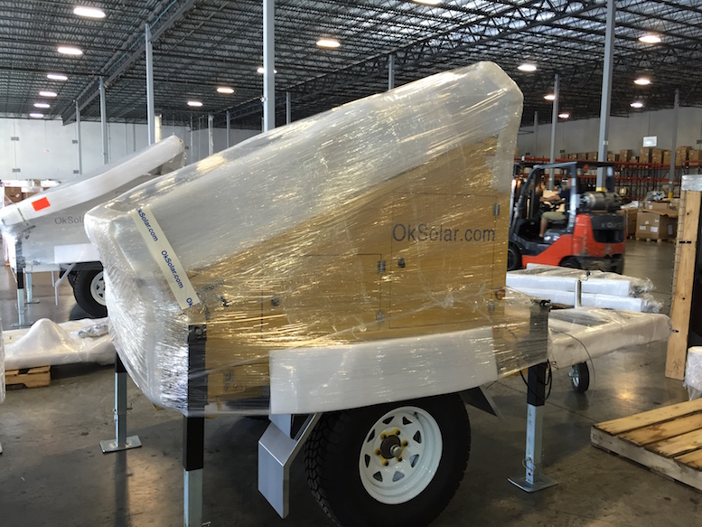
Sample Ready to ship unit


 Note:
To view the above PDF documents, you will need the
free Adobe Acrobat
Reader
Inverters, Inverter/Chargers, Smart Battery
Chargers, Emergency Backup Power, Tripp-Lite,
tripplite, tripp lite, exceltech, iota, Outback,
Inverters,Vanner, Sunny Boy, trace, xantrex, AC
Inverters and Accessories !
![]()